Digital Voltmeter- Principle, 4 Basic Types, Applications, Merits & Demerits

Digital Voltmeter is a device that lets you display the potential difference of the circuit. But there are more things that a digital voltmeter can do.
And, this is what we are going to find in this post. We discuss various types of the digital voltmeter, the principle of it, advantages, disadvantages, along with their application.
What is a Digital Voltmeter?
Digital Voltmeter (or we say DVM) is a piece of electrical equipment that is useful in obtaining the value of potential difference that is flowing through the circuit. And the best part is that a DVM can measure both the alternative current (AC) and direct current (DC).
However, in all means, it first measures the input voltage as analog voltage then transforms it into the digital form which is represented by the numerical values. This transformation is done by an integrating converter.
Moreover, one of the governing factors is the accuracy and speed which is again governed by various other factors such as temperature, input impedance, and DVM power supply voltage variations.
Note: The first DVM was invented in 1954 by Andrew Kay.
People Also Read:
- How to Hotwire a Car? | 3 Best-Known Cheat to Hotwire a Car
- Step-Up Transformer: Principle, Application, Advantages & More
How does a Digital Voltmeter (DVM) Work?
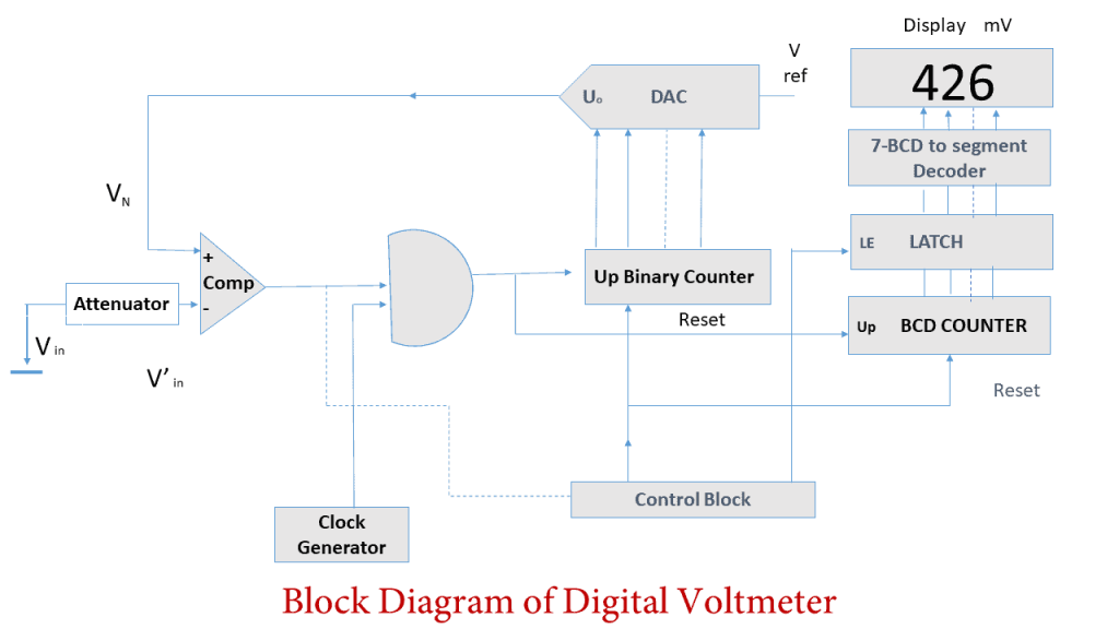
To explain the working of a digital voltmeter uses, we have categorized it into different sections. And based on each section, we describe its process of working.
In short, the following is the conclusive-cum-conceive working form of the various sections of a DVM.
- Input signal
- Pulse Generator
- Voltage Control and Gating
- Counting Clock Pulses
- ADC (Analog to Digital Converter)
- Decimal Display Panel
Input Signal
With the use of live circuit connection points of a DVM, the input voltage is brought into contact. And with this, the actual working of a DVM starts.
Pulse Generator
After the voltage impulse brought inside a DVM, a pulse generator is used to convert the analog voltages into rectangular pulses.
In addition, a pulse can be measured using either the digital or analog pulses. But in sophisticated DVM, they use both analog and digital techniques to convert the input voltage into rectangular pulses.
These rectangular pulses are controlled by two governing factors.
- Digital circuitry controls the width and frequency
- Analog Circuitry controls the amplitude and rise and fall time
Voltage Control and Gating
After getting one leg signal from the pulse generator, the other leg is controlled and gated by a comparator.
For instance, a comparator compares two voltages and outputs the largest voltage. So, here a comparator uses one leg voltage impulse from the pulse generator and another from input volt (Vin) and compares it for the largest.
Additionally, the comparator is equipped with another chip called Operational Amplifier (Op-Amp) to achieve a near-zero input current which is labeled as +ve (non-inverting) and -ve (inverting) inputs.
Counting Clock Pulses
In this phase, the number of clock pulses is counted on the measures of escaped time. These pulses are interpreted and counted with the help of an IC chip. This IC chip now generates a string of binary numbers with the pulse value of 0 to 9.
For instance, all the digital voltmeters share the same principle of counting the pulses with respect to time the capacitor starts charging. In doing so, when the capacitor voltage overrides the input voltage, it changes the output state with the help of a NAND gate. The one port of the NAND gate is connected to the train output pulse while the second is connected to the internal control unit system.
When a current is passed through the capacitor it turned-on and off accordingly. And this process of charging and discharging continues— this is also called the heart of digital voltmeter. Therefore, with each occurrence of pulse, a corresponding binary bit is generated.
Integrated Analog to Digital Converter (ADC)
As per the name, an Analog to Digital Converter (ADC, A/D, or A-to-D) converter converts an analog signal to digital data. In this case, ADC converts the continuous-time and continuous-amplitude analog signal to a discrete-time and discrete-amplitude.
ADC finally represented this discrete data into a digitized number which is usually the binary numbers.
Digital Voltmeter Display Section
After getting data from the ADC convertor, a piece of special equipment called “latch” which interprets the data statistically. The resultant counts of impulses are going through necessary calibrations. This finally displays over the LCD and LED digital voltmeter display section.
Types of Digital Voltmeter (DVM)
While talking about digital voltmeter types, it is categorized into four major divisions. These are:
- Ramp Type Digital Voltmeter
- Integrating Digital Voltmeter
- Dual Slope Integrating Digital Voltmeter
- Successive approximation Digital Voltmeter
Ramp Type Digital Voltmeter (DVM)
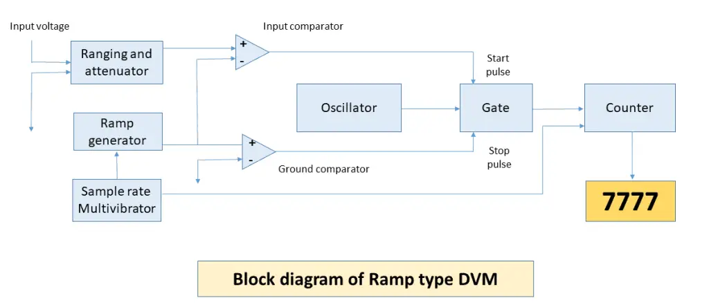
When the input voltages are interpreted with the means of time with zero voltage then it is a ramp type digital voltmeter.
The principle behind this equipment is simple, it takes the value of input voltages and measures the time to take input voltage to reach zero volts or vice versa.
Therefore, based on the time intervals between the intervals of reaching ramp voltage to the level of input voltage and then to zero is displayed. And finally, the value is displayed on the display of VDM.
Integrating Type Digital Voltmeter
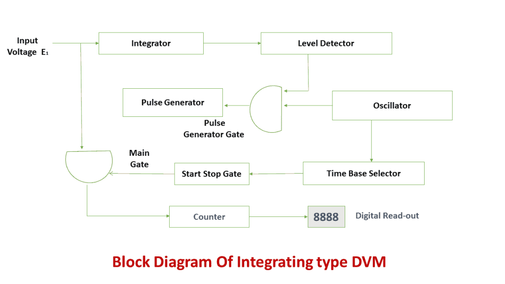
In an integrating type of digital voltmeter, a voltage to frequency converter acts as the bases of its working. But the values are evaluated on the basis of fixed measuring time.
So, when the input voltage is fed into an integrating type of digital voltmeter, it first gets converted into the respected frequencies that are proportional to the magnitude of the source voltage.
In doing so, a string of train pulses is generated which are then being counted with definite time intervals. And the resultant values are displayed on the LED or LCD display.
Dual Slope Integrating Type Digital Voltmeter (DVM)
On the application of analog voltage input, the integrator comparator increases the input volts to a reference point which is usually to some positive value.
Meanwhile, the time intervals are used as measures to interpret the rate of increase (or decrease) in voltages. This interpreted value is proportional to the input volts. And this is what the principle of integrating type digital voltmeter (DVM) is.
After that, the value tends to decrease and again the time is measured until the volt reaches the bottom reference point. The resultant count is then displayed on the digital voltmeter display.
Successive Approximation Digital Voltmeter (DVM)
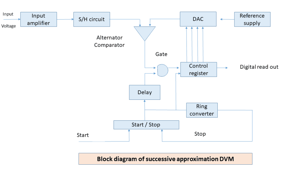
In a successive approximation DVM, an advanced analog to digital converter is employed which is very sensitive and is able to read 1000 readings per second.
So, when the source input voltage is passed, it goes through an on/off multivibrator. The resultant value is then passed through a control register set which is usually set to a high while all other bits are set to low. Therefore, if the DVM has an 8-bit control register, the reading would be 8-digit. And based on the approximation data, the value would be 10,000,000.
In general scenarios, the resultant output value should be half of the reference volts. After that, a comparator is employed which compares both the volts and produces the output that retains value 1 by the control register.
Now, due to the use of an additional ring converter, the count got an additional ‘1’ and a decremental zero from the end (so, the value would be 11000000). And on reaching the last count, the cycle stops. And this is how a successive approximation cycle works. Henceforth, the resultant value is shown on the DVM display.
Applications of Digital Voltmeters (DVMs)
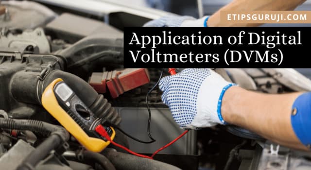
As from now, you will know that digital voltmeters are used to measure the voltages. But there are more things that you can do with it. Let’s check them.
The Voltmeter Applications are as Follows:
1. Check your car batteries or other equipped batteries like AAA and AA type batteries. It is also a handy tool for the car owners who can check for any circuit failure.
2. Troubleshooting the projects: Even if you are not an electrician, a DVM is a must-have equipment that troubleshoots various problems that you might encounter at home or work. This would help you to find the cause of any circuit break.
3. And if you just want to know the value of volt that is flowing in other circuits you can also evaluate their volts with a voltmeter.
4. A DVM can also be used to measure the Pulse Width Modulation (PWM) signal of the source.
5. They are also used as a continuity checker with a series of batteries.
6. A DVM can be used to build ohmmeter with the unknown resistor in school projects.
Advantages of Digital Voltmeter (DVM)
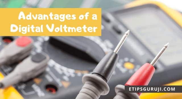
These are the following advantages of a digital voltmeter:
1. Eliminates Human Error: With the digitized numeric value, which is in decimal form, a human can easily read the volts value without any chance of misinterpretation.
2. More Accurate: A digital voltmeter can give a reliable and accurate result with a minimum chance of operating error. In the general case, a DVM has an accuracy of 0.5% + 1 digit with a temperature between -5 ⁰C to 55 ⁰C.
3. Cost-Effective: A sophisticated DVM can cost less than $10 which is clearly a small price for this handy tool.
4. Smaller in size: They are generally available in various sizes. But majorly, the general size of a DVM is about the size of a 6” smartphone. Moreover, they are also slim and lightweight.
5. AC and DC Compatible: A digital voltmeter is capable to measure both types of DVM volt i.e. AC and DC volts.
6. Store Reading: With the recent developments, the latest digital voltmeters can store reading. So, that you can use them later for referencing the values.
7. High Input Impedance: With this, you can measure high input impedance (opposite of current), both static (resistance) and dynamic (reactance) value.
Disadvantages of Digital Voltmeter (DVM)
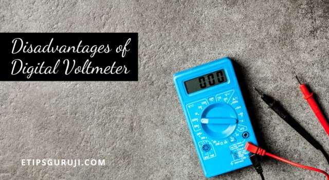
Now, let’s find out some disadvantages of a voltmeter. These are:
1. Unlike analog voltmeter, there is no need for external power sources. But if you have a digital voltmeter, you have to add an external power source (battery) to get the display output.
2. The optimum temperature of the digital voltmeter is -5 ⁰C to 55 ⁰C, so if the DVM is constantly being employed, you might get a wrong reading because of overheating issues.
3. A DVM can state the wrong value due to the noise of their integrated part such as the A/D converter.
4. If the voltage value goes beyond the operation range, there is more chance that it could get damaged.
5. A DVM is unable to read the fluctuation of the digital voltmeter.
6. Moreover, if you are employing it to find a peak voltage value then it might be hard for you.
Also read:
- Types of Transformer (Categories Wise) – Working and their Applications
- How to Test Capacitors – Its Methods, Functions, and Types
Digital Voltmeter and Ammeter
To state about the working of both of the electric equipment, we have formulated a table for you. It would help you get a better overview of both.
| Quality | Digital Voltmeter | Ammeter |
|---|---|---|
| Definition | A type of device through which the electrical potential difference between two points is measured of any electric circuit. | An ammeter is used to measure electric current in any device (an electric circuit) |
| Installation | Always in parallel | Always in series |
| Measures | The voltmeter measures the voltage parallel to the current | An ammeter measures the current in series. |
| Range | The range can be changed | Range in ammeter cannot be changed |
| Accuracy | More accurate than an analog voltmeter | More accurate than a digital voltmeter |
| Resistance | The voltmeter has more resistance. | Ammeter has less resistance. |
General FAQs
What is AC digital voltmeter?
These are the digital voltmeters that can measure the potential difference (peak of the AC current with the corresponding resistors) of the AC source input.
How to use a digital voltmeter?
To use a digital voltmeter, you have to first attach two legs to the naked circuit wire or the terminal. Now, it simply displays the values in their read-out unit. However, in some cases, calibration is required before using it for the first time, after every startup.
How to read a digital voltmeter?
After the application of two legs of DVM, the output volt value is displayed on the LED or LCD display. The display represents values in decimal volts such as 5.4v, 12.0v, etc.
How to wire a digital voltmeter?
To wire a digital voltmeter, you should connect it in parallel to the circuit with the two-leg of it connecting to the positive and negative terminal of the circuit.
